It’s the age old manufacturing quest … how to reduce the cycletime and machine parts faster. And although cycletime is a major factor in the making profits equation … concentrating too much on cycletime can sometimes make you miss the bigger problems … the bigger deficiencies in the shop … the bigger money wasting issues. While you are trying to shave seconds off the machining … the time your machine spends not running is hands down a much bigger problem. Any machine not cutting is burning money and profits. It’s easy to focus attention on cutting speeds and feeds … it’s a fairly obvious item especially for non-professional metalworkers. The fact is, however, every second or even minute you shave off the cycletime is probably no match for the large quantity of time you’re machine spends not machining.
What is the BIGGEST cause of your machine not cutting chips ??
The biggest contributing factor for shop machines not cutting chips and therefore making money ( other than not having work for the machines ) are primarily load / unload operations and changeover of the machine from one job to another.
We are starting a new series here in our CNC MACHINIST BLOG to deal with these biggest money wasting areas in almost every shop … fixturing and workholding. Whether it’s the time needed to changeover the machine from one job to another … or the time required to load and unload the part … non-machining time is the biggest profit killer in any shop.
To start things out … I would invite you to take a walk out to your shop floor … and count the number of machines that are running? … how many IN-CYCLE lights are lit? I am betting you will be amazed at what you find. And if you look deeper into why the machine is not running … the reasons can usually be classified into two categories. The machine is being set-up to run production … or the workpiece is being loaded for machining.
Everywhere people are jumping on the “lean” manufacturing bandwagon … as they should … and striving to achieve the 80%-85% percent “in the cut” time target. The fact of the matter is that lean manufacturing goes well beyond just direct chip making. The time spent … or lost … in changeover or part loading / unloading … is probably a bigger profit losing factor than the time the tool spends in the cut.
This series will pull from our shop floor experiences to talk about the various areas of workholding for both milling and turning and machine / fixture changeover … two topics that are certainly inter-connected. We will publish new articles interspersed with our other topics of interest … so we invite you to check back frequently and keep up with the discussion.
Series Topic #1 :
Bringing The VMC Machine Table
Into the 21st Century
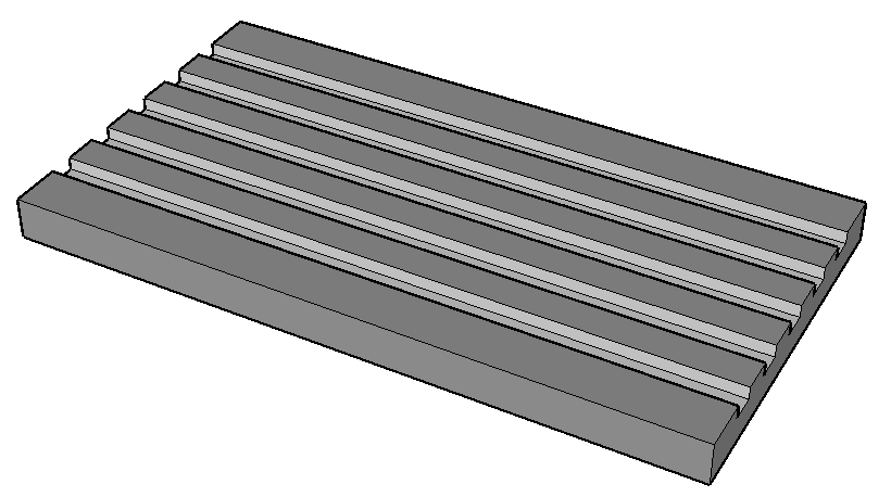
If you take a look at the table on your new VMC … and compare it to the table on a 1940’s milling machine … you’ll quickly notice that not much has changed. T-SLOTS, T-SLOTS and more T-SLOTS. Not much has changed in the design of the milling machine table since around 1940 … and that’s our first issue to tackle.
While no one will deny that the T-SLOT is an essential element in the table design … in today’s day and age we really need to think outside the box … or in this case outside the T-SLOT. A couple flaws enhanced by relying on the T-SLOT design include not utilizing all of the space available in the Y axis … and not having the flexibility of positioning fixturing anywhere on the table to maximize the whole table surface. The first step in accomplishing this is to change the table surface.
One way of altering the surface of the machine table is to use a sub-table … made from aluminum tooling plate or other suitable material. The main criteria is that the material is durable … while being fairly easy to machine because we will want to machine a variety of locating options into the sub-table. The two biggest advantages with a sub-table as mentioned above is that we now have the freedom to machine locating components to accommodate a wide variety of fixturing … we can more easily utilize all the area of the table surface … and we can always remove the sub-table and go back to the original table configuration if required.
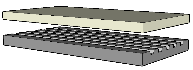 Some of the major points for consideration when considering a sub-table and it’s design :
- Material : durable yet fairly easy to machine … aluminum tooling plate is one recommendation.
- Size : it should cover the majority of the table … thickness should be kept to a minimum as to not reduce the Z axis travels by an unreasonable amount … but thick enough to accommodate our locating components and maintain rigidity.
- Weight : aluminum will keep the weight down … but lifting components should be included in the event the sub-table needs to be removed or re-installed.
- Locating the sub-table can either be done with keys machined into the bottom surface or with the use of locating pins and dowels that can be used in conjunction with the original table T-SLOTS.
- Once the table is installed … it may be necessary to skim the top surface to insure it’s parallelism with the machine axis. Keep this in mind when determining the size of the plate and the travels of the machine to allow for this type of machining. Periodically … this may have to be repeated if excessive wear of the table surface occurs. Also make sure to account for this when selecting and installing your locating components … which will most likely be hardened materials and not easily machined … and will need to be installed below the top surface of the sub-table.
Best Ways to Utilize Your New Table Surface
Now that you have transformed your table surface into a 21st century table … how can you get the most out of it? That really is only limited now by your imagination and design capabilities … but here we will tackle what we would consider the top option.
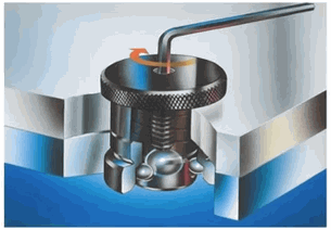
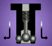
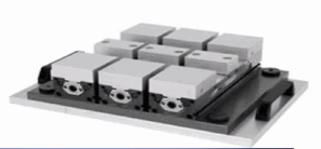
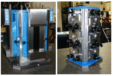
Our recommendation … we have used this system extensively … is to utilize fixture plates located and clamped by a “ball lock” system. Fixture plates should be used for everything mounted to the sub-table … from a simple vise to multiple vises to dedicated fixturing. This allows for greater flexibility for positioning of workholding components and allows for quick changeover to other workholding components.
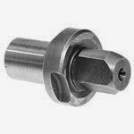
The ball-lock system allows for quick and accurate positioning of the fixture plates to the sub-table. When designing the sub-table surface … create as many ball-lock receiver positions as possible to allow for multiple positioning options for your various fixture plate assemblies. You can machine and install these receivers prior to mounting the sub-table … but they can also be machined in place as their need arises.
Fixture plates can also be made from the same aluminum tooling plate material used for the sub-table. They should, of course, be quite thinner for weight considerations and should always include some kind of lifting component. Handles, as the ones included in the illustration, may need to be removable with a quick attachment mechanisms to reduce their interference in the machining motions.
If you have an HMC … you can take the same lessons learnt here and apply them to your tombstone or angle plate. Rather than using the standard “vise tombstone” … a tombstone which utilizes fixture plates can open up new possibilities for your HMC as well.
Changeover Advantages
As mentioned above, the cycle start light goes out and the profit stops flowing when the machine is being changed over from one job to the next. The system described above can have a massive impact in reducing that downtime. Take for example the simplest task of working with a vise. To remove the the vise … just un-clamp the plate with the vise and remove it. When re-installing it … just lock the plate with the ball-lock system … no tramming … no indicating … no center locating. The ball lock system locates the vise in a known position in seconds every time.
The same applies for all your fixtures … they mount in seconds in known positions. Fixture design will also be improved because the know facets of the fixture plate location and much of the needed configuration is pre-determined. With pre-set variables in place … your engineering mind will run rampant and you’ll be exploring many more time and money saving options as you go down the road.
Seems Like a Lot of Work and Expense
The above statement is true … but it’s not easy to get from 1940 to the 21st century. The fact is that once you have completed the transformation … the possibilities for added efficiency are endless and the reduction of lost machining time will be fantastic … the payback and ROI will be fast. You will have new flexibility to :
- Utilize more of the machine table and Y axis available stroke … more chip making means more profit.
- Quickly and easily mount your fixture plates making for faster changeovers … which means more time cutting chips … and making money.
- Have new capabilities to mount multiple jobs with multiple fixture types … easily run more than one job at a time.
- If utilizing a 4th axis … the new table design will give you more positioning options and result in faster mounting and removal of the 4th axis table.
Final Thoughts and What’s Next
As you can see from some of the ideas outlined here, changing the surface design of your machining center’s table can have quite an impact. While everyone is concerned with shaving seconds of the chip making … shaving hours off your set-up’s and changeovers will have an even greater impact on your bottom line. We hope that some of the ideas outlined here spur on your engineering juices allowing you to realize even more efficient fixture designs and ideas.
Make sure to return and check out other articles in this Series that will deal with fixturing and workholding … for both turning and milling. We’ll touch on things like vises … face drivers for turning … chucks and chuck workholding … and much more.
After all … we’re MACHINISTS … WE BUILD THINGS !!
At Kentech Inc. we are MACHINISTS who create Real World Machine Shop Software. Who creates the machine shop software guiding your shop’s future ??
Check out all our REAL WORLD CNC & MACHINE SHOP titles at www.KentechInc.com
Kenney Skonieczny – President
Kentech Inc.

