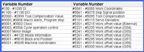
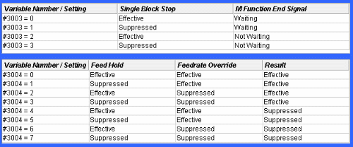
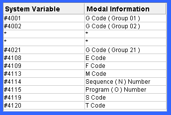
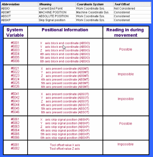
The last type of Fanuc Macro Variables we will cover in our series are called SYSTEM VARIABLES. System Variables are fixed variables and read and reflect on conditions or values found somewhere in the CNC system. There are a variety of System Variables available to the user but they can for the most part be classified into some major groups :
INTERFACE SIGNALS :
The status of various input / output signals can be read using System Variables #1000 thru #1035, #1100 thru #1115 and #1132 thru #1135. Users should consult with their own individual electrical diagrams as specific input / output signals can be designed differently by different machine tool builders. But the general configuration looks like this :TOOL GEOMETRY OFFSET VALUES :
Tool offset values as well as work offset values can also be read and modified through the System Variables as well. Those variable configurations look like :WORK OFFSET VALUES :
Work offset values … G54 thru G59 … can also be read and modified through the System Variables as well. Those variable configurations look like :ALARM GENERATION :
Users have the ability to generate ALARMS with user defined message using System Variable #3000. The format for using System Variable #3000 is :
#3000 = XX ( error message defined here )
In the above format … XX is the error message # ( must be less than 999 ) and the error message to display is defined between the ( ) . For example :
#3000 = 123 ( ERROR ENCOUNTERED )
When the macro program executes the line as above, the machine would enter the alarm condition … the CRT will display Error #123 followed by the message ERROR ENCOUNTERED. Clearing the alarm condition is as normal.
The user has complete control over the Alarm # and the message to be displayed.


