One of the best ways to add efficiency to your CNC lathe is to make it run unattended. Using a bar feeder or a simple bar-puller, you can make your lathe run in a more complete AUTO cycle, stopping only for the refilling of the stock and minor offset adjustments. In this article, we’ll share a simple but efficient design for a bar-puller and show you a programming example of how to put it to use.
Granted, a little work is required but when put to the right use, unattended operation can really help your bottom line. For example, how about being able to leave the shop at 5:00 and still have your lathe running producing another 50-60 parts while you’re home eating dinner. Or for the one man shop, how about having production being run while your on the phone getting that next deal. With the right combination of cutting conditions and unattended operation, there’s no telling where you can go.
The CONCEPT
The idea behind this bar-puller is to fill the spindle with a bar length of material, then using an auto cycle perform the following sequence :
- Grab the stock with the puller
- Open the chuck
- Pull the stock to the desired length
- Close the chuck
- Retract the puller
- Machine the part
- Cut-Off the part
Then simply repeat the cycle again, the number of times for repeat depends on the number of parts that can be made using the length of bar stock in the spindle.
The SET-UP
To create your bar-puller feature, you’ll need a couple of other items other than the bar puller to be outlined here.
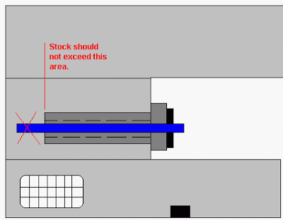
First, you’ll need to cut the bar stock the length of your spindle so the stock can be slid inside your spindle and pulled by the bar puller through the chuck or collett nose in the front. NEVER, NEVER, NEVER hang any size stock outside the end of the spindle – all stock must fit inside the spindle housing and be supported with spindle liners or a support ring as outlined below.
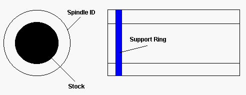
Since the difference between the stock OD and the spindle ID is usually pretty big, you can’t just put the stock in the spindle. It must be supported in the spindle to prevent the stock from rattling around. This can be done with commercially purchased spindle liners or you can make a simple spindle liner ring using the design and concept outlined here. Please note that these liners take up the “slop” between the stock size and the ID of the spindle and must be used to prevent possible whip or damage to the spindle bearings or other possible injury.
One method is to make a ring out of plastic or similar material that attaches to the end of the stock with a set screw. The OD of the ring fits snuggly into the spindle ID and the ID of the ring attaches to the OD of the stock. This ring will move along the inside of the spindle along with the stock as it gets pulled toward the chuck. Calculate the number of cycles so this ring will reach the end of it’s possible stroke as the max count is reached.
The BAR PULLER
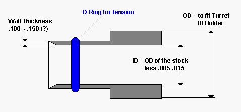
Now the homemade bar puller needs to be made. The concept behind this puller is that you can make the size required as needed for the size material you are currently working with. You can make a few at a time, leaving some finishing operations until the ID size is determined. This way you’ll have maybe 70% of the puller made then you can simply finish the rest when the time approaches and the final sizes are determined.
The bar puller uses a “split” piece of aluminum or other material softer than the material you will be machining. It uses simply a piece of bar or tube that is machined with the OD to fit into an ID tool holder station in the turret, and the ID slightly smaller than the OD of the stock. You may need to turn down the front end as per the sketch below to maintain a wall thickness that is thin enough to slide over the stock when split yet strong enough to pull the bar, depending on the weight of the bar stock determined by the diameter of the stock. The puller is then split in two or three or more places using a hack saw or slitting saw and an O-Ring placed on the OD of the puller to keep the tension. This allows for the puller to split and feed over the bar stock with the O-Ring providing tension to pull the stock and for the puller to return to it’s original shape when done.
The PROGRAM
In the program, the puller is mounted in the turret, in our example Tool #3. Then in the CNC programs AUTO cycle, it is fed over the bar stock, the chuck opened, the turret moved to position taking the stock with it, the chuck closed, and the machining begun.</P><P>In the example below, we are simulating a Fanuc series 10T or higher CNC control. Your M functions may be different, please consult your programming manual for your specific commands. Use this program as a guide, not a bible. The X0 is the center line and Z0 for this tool is set at the face of the stock as it sticks out of the chuck after cut off.
N0001 ————— sequence number for this operation
M05 —————– make sure the spindle is stopped
G00 T0303 ———- index to the bar puller station
G00 X0 Z.200 ——- rapid to a clearance point
G98 —————– change feed to IPM
G01 Z-.750 F20.0 — feed onto the stock
M11 —————– open the chuck
G01 Z2.000 ———-feed to needed length plane
M10 —————– close the chuck
G01 Z3.500 ———- feed off the stock
G00 X8.00 Z8.00 —- rapid to index position
T0300 ————— cancel the tool offset
G99 —————— return feed to IPR
M01 —————– optional stop
This sequence should be placed at either the top or bottom of the machining program. The best way to put the AUTO cycle into use is with the use of sub-programming. The MAIN program would be the call for the machining program including the number of times to call the program depending on the number of pieces you can make from the length of bar stock in the spindle. The SUB program would actually do the pulling and the machining. For example, in the example below, program O0001 is the MAIN program, calling the SUB program O1111 – 12 times, which actually does the pulling and the machining.
O0001 ———— Main Program
M98 P1111 L12 — sub program call
M30 ————— program end
..
..
O1111 ————- Sub Program
N0001 ————- Bar pull sequence
—
—
—
M01
N0002 ————- machine the part
—
—
—
M01
N0003 ————- cut off
—
—
—
M01
M99 ————— sub program end
In the above example, the operator only presses the Cycle Start on the MAIN program. This starts a 12 piece cycle that will include the pulling out of the stock, the machining of the part, and the cut off of the part. Recalling and executing the cycle 12 times.


